Model H
Replacement controller board for IBM Model M
Project maintained by jberclaz Hosted on GitHub Pages — Theme by mattgraham
Model H - Build Tutorial
Replacement controller board for IBM Model M Keyboard
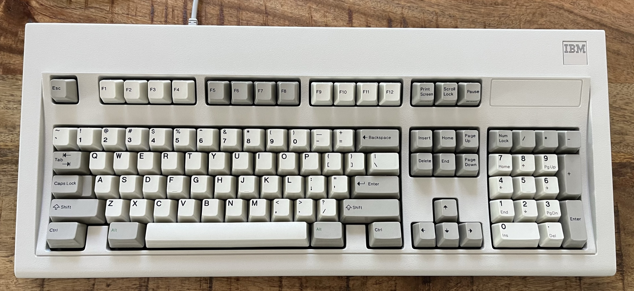
The IBM Enhanced Keyboard (Model M) is widely considered the best keyboard for its typing experience. First produced in 1985, it was made of high quality materials and is very durable. IBM produced over 10 million units, and because of their durability, there are still many working keyboards today.

However, those keyboards were originally designed for the PS/2 port, which is rarely seen in recent computers. Some units that were shipped with terminals even used a RJ-45 interface. As a result, it can be difficult to use this keyboard with modern computers.
If you want to enjoy the great typing experience of an IBM Model M on a modern computer, you have basically 3 options:
- You can buy a new unit with a USB interface at Unicomp.
- You can use an active PS/2 to USB converter. That solution will not work for RJ-45 Model Ms, though.
- You can replace the original controller with a new one supporting USB. That is what this project is about.
Of these three options, building your own controller is the most complex, but offers the greatest customization. You’ll end up with a native USB connector that is very well integrated with the keyboard.
In addition, the controller firmware uses QMK, which allows you to remap your keys. This is very handy to add media keys and other custom combinations you may need.
This project requires no prior electronics design knowledge, but basic soldering skills and familiarity with command-line tools are helpful. Beginners can follow along with the provided tutorials.
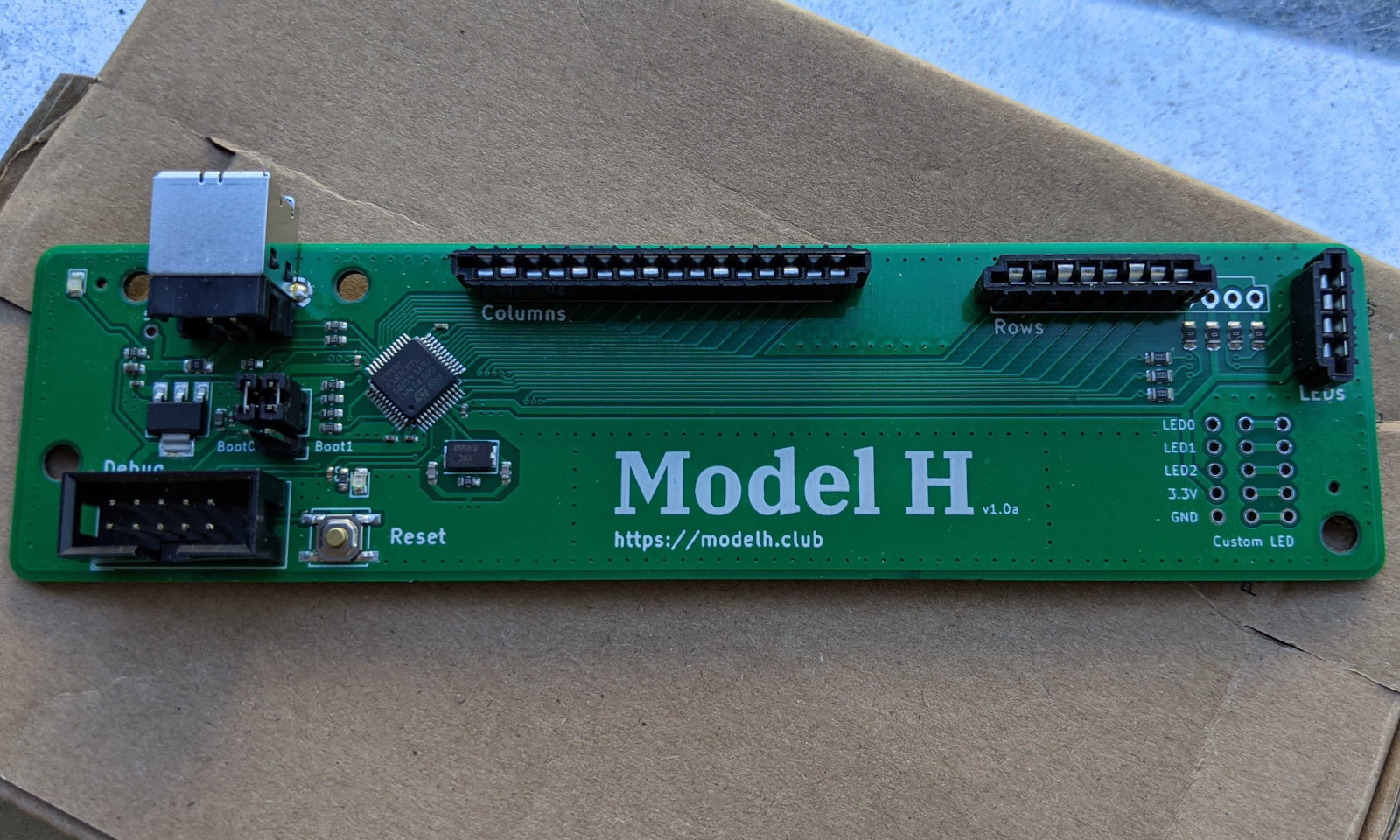
This repository contains the open-source PCB design for a replacement controller board for the IBM Model M keyboard. It was designed by John Hawthorn. The controller is a drop-in replacement for the original controller, which includes USB support and modern QMK-based firmware. It can be installed without any modification to the keyboard and can be fully reverted.
Related work
This work is not the first attempt at a replacement controller for the Model M. Here are a few related projects:
-
Michael Schwingen’s controller - One of the earliest open-source designs, featuring an ATmega32u4 with port expanders, bootloader button integrated into the USB housing, and optional RGB LED replacements.
-
Model-M-Type-C - Emphasizes native USB-C and hotswappable design with QMK compatibility; the USB connector is placed externally using a 3D-printed dock to fit inside the case.
-
Yacobo - Built around the inexpensive Blue Pill (STM32F103C8T6) development board as the microcontroller, requiring users to source and solder the board themselves.
-
Model-H-Rmx - A fork of the original Model H with a notched PCB shape for broader case compatibility, on-board solenoid support, and grouped testpoints for easier debugging.
-
ctrl-M - Based on the STM32F072, supporting four different LED connector variants and designed to fit even the smaller later-model PCB variant.
-
Model-X - A wireless controller adding Bluetooth Low Energy alongside USB Type-C; built on the nRF52840 with ZMK firmware and a 2000mAh battery lasting over a month.
Building the Controller Board
In this tutorial, we will go into all the steps needed to make your own Model H controller board. Note that I assume you’ll be using Linux (specifically Ubuntu). You can probably accomplish it under Windows if you install the WSL. However, I have not tested it.
PCB
Here, we show how to produce the PCB with JLCPCB. There are many similar providers. Feel free to choose a different one. Note that the bill of material has been optimized for parts available at JLCPCB. Should you choose a different provider, you might have to replace some parts.
- Go to JLCPCB and create an account.
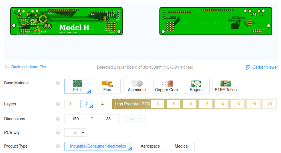
- On the JLCPCB home page, use the button
Add gerber fileto upload the filegerber.zipfound in theproductionfolder of this repo. You should see a page like the image below. Leave the default options.
- At the bottom of the page, select
PCB Assembly. Leave the default options, but you may want to change thePCBA Qtyto 2. Also, selectYesforConfirm Parts Placement.

- On the right of the page, click on
NEXT. -
You can now visualize both sides of your PCB. Then click on
NEXTand upload the two filesbom.csvandpositions.csvfrom theproductionfolder. - Click on
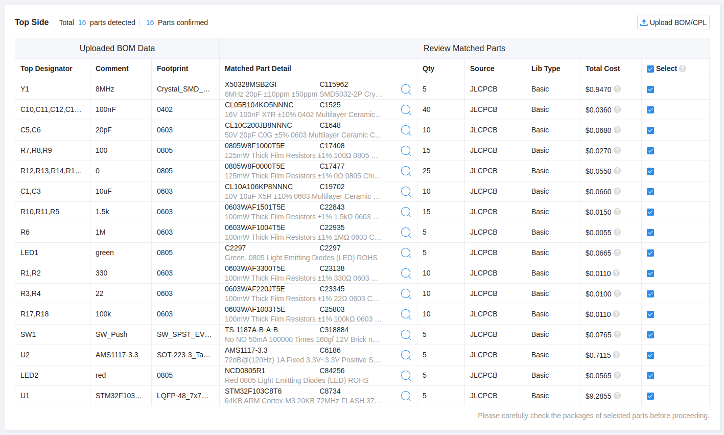
Process BOM & CPL. At this point, you should see a list of all the components for your design. If all of them are available, clickNEXT. All components were selected from JLCPCB’s basic parts to ensure availability. However, if a part is temporarily out of stock, you can select a replacement using the magnifying glass icon or wait for restocking.
[!NOTE] It was reported that the STM32F micro-controller has been moved from Basic Parts to Preferred Extended Parts. It will still work as expected, but might become a bit more expensive.
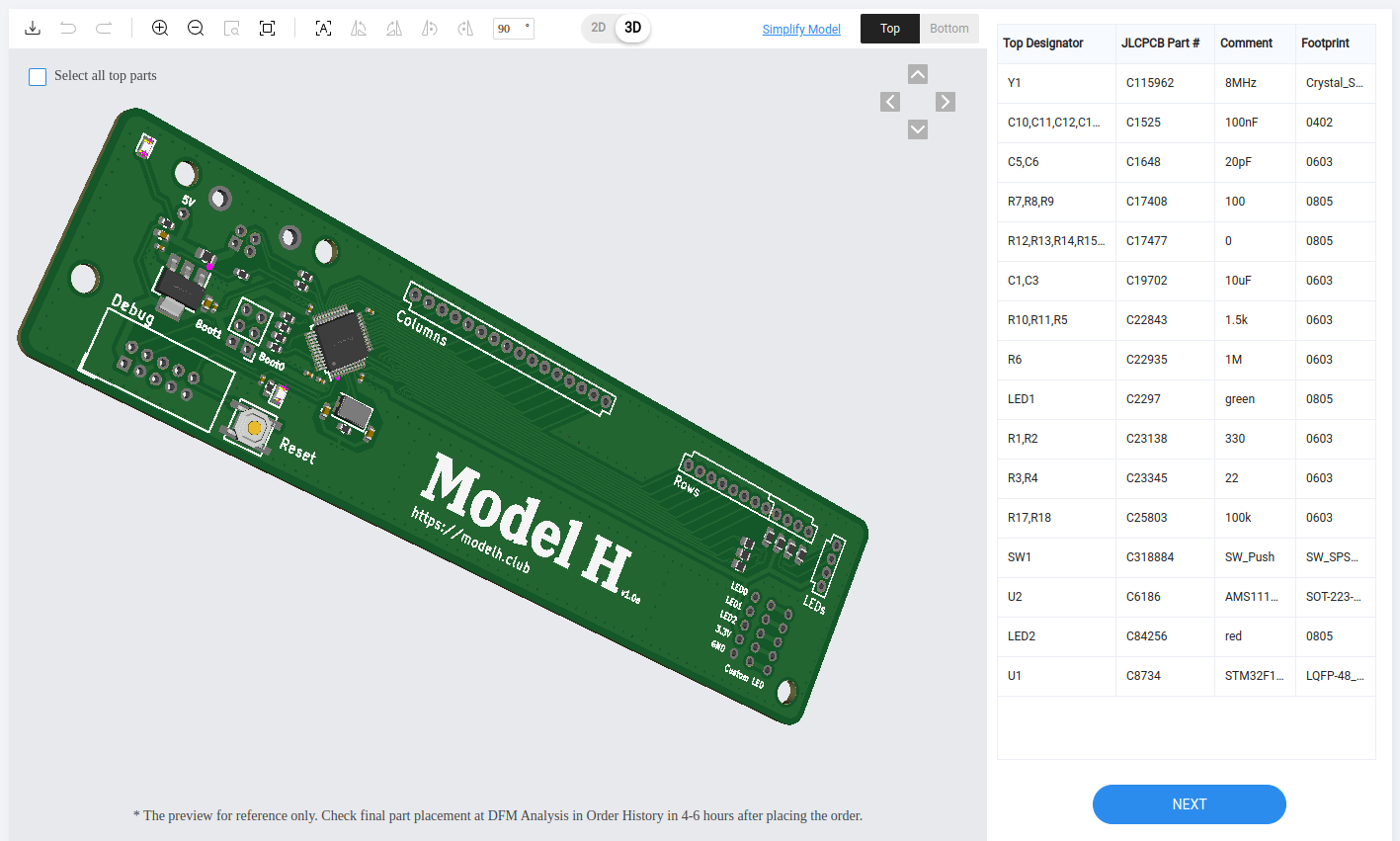
- This page should show you the parts placement (as shown below). Select the 3D view and verify that the components are placed properly. Then click
NEXT.
-
Select Product Description: Office Appliance…/Keyboard…
-
Save to Cart, Check Out.
Cost
At the time of writing (May 2023), the cost of 5 PCBs with 2 assembled was $21 (without shipping).
3D Printed connector spacer
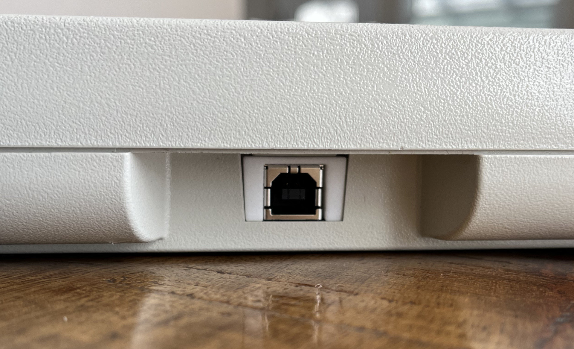
To maintain the USB connector and the controller board in place, you will have to 3D print a small connector spacer to be inserted around the USB connector.
The file to be printed is located at shim/shim.stl.
You can use any 3D printing service for this, however you may wish to order from JLCPCB to combine shipping with your PCB order.
Additional Components
While you wait for your PCB to be fabricated, you can order the few additional components that you’ll need to hand solder onto the board. Before ordering additional components, disassemble your keyboard to determine the specific connector type used for the LEDs. Refer to this tutorial for disassembly instructions.
There are several types of connectors for the LEDs.
- If your keyboard does not have LEDs, you will only need a 16-position and a 8-position FFC connectors.
-
If you have an old keyboard with the type of LED cable shown below, you’ll need a S4B-EH connector (thanks @Wh1terat). In addition, you’ll need a 16-position and 8-position FFC connectors.

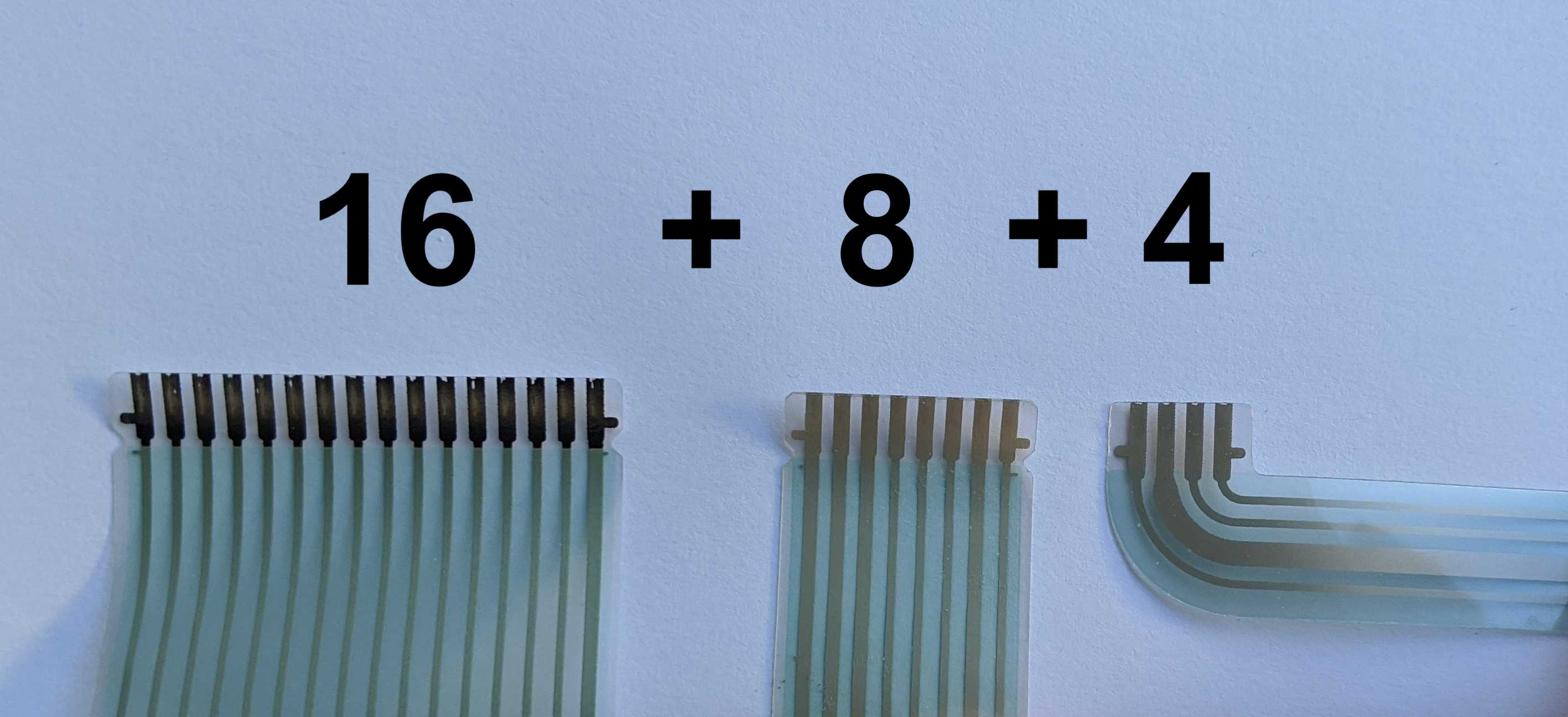
-
If your LEDs are connected with a FFC cable like the one shown below, you’ll need a 16-position, 8-position and 4-position FFC connectors.
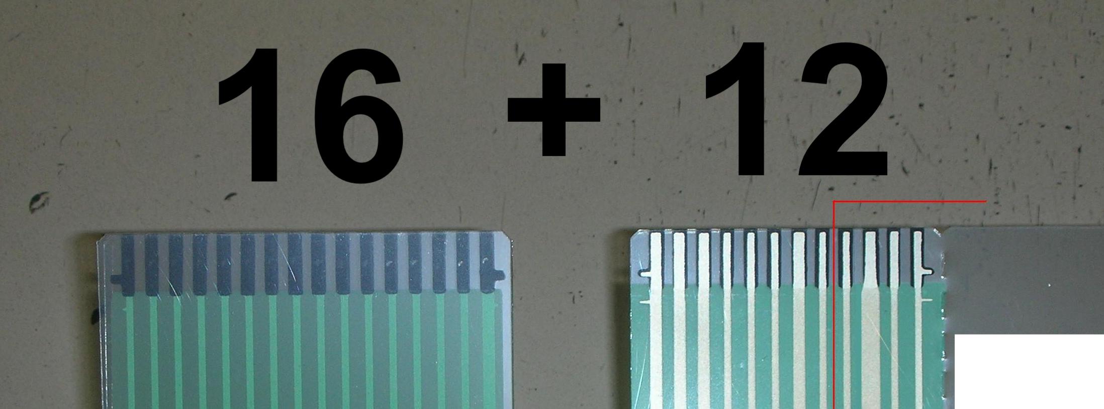
- Finally, if you LEDs are integrated to the membrane rows connector (see below), you’ll need a 16-position and a 12-position FFC connectors.
Below is the list of components you will need to order:
| Part | Link | Quantity |
|---|---|---|
| 16-POS FFC TE connector | https://www.digikey.com/en/products/detail/te-connectivity-amp-connectors/6-520315-6/688643 | 1 |
| 8-POS FFC TE connector | https://www.digikey.com/en/products/detail/te-connectivity-amp-connectors/5-520315-8/688639 | 0/1 |
| 4-POS FFC TE connector | https://www.digikey.com/en/products/detail/te-connectivity-amp-connectors/5-520315-4/2262309 | 0/1 |
| 12-POS FFC TE connector | https://www.digikey.com/en/products/detail/te-connectivity-amp-connectors/6-520315-2/1137020 | 0/1 |
| USB-B connector | https://www.digikey.com/en/products/detail/te-connectivity-amp-connectors/292304-1/773785 | 1 |
| Debug port connector | https://www.digikey.com/en/products/detail/on-shore-technology-inc/302-S101/2178422 | 1 |
| 6-POS header connector | https://www.digikey.com/en/products/detail/w%C3%BCrth-elektronik/61300621121/4846835 | 1 |
| jumper | https://www.digikey.com/en/products/detail/w%C3%BCrth-elektronik/60900213421/2508447 | 2 |
| USB A-B cable | https://www.digikey.com/en/products/detail/tripp-lite/U022-006-BE/7104962 | 1 |
| S4B-EH connector | https://www.digikey.com/en/products/detail/jst-sales-america-inc/S4B-EH/926535 | 0/1 |
Cost
Less than $10.
Soldering
Once you received the controller board and all the components, it’s time to solder them to the board. With the proper technique, soldering is achievable even for beginners. This tutorial goes in a lot of details and the video explains very well how to easily solder your through-hole components into the board. If you’ve never soldered before, I would recommend practicing on a different board before assembling your Model H.
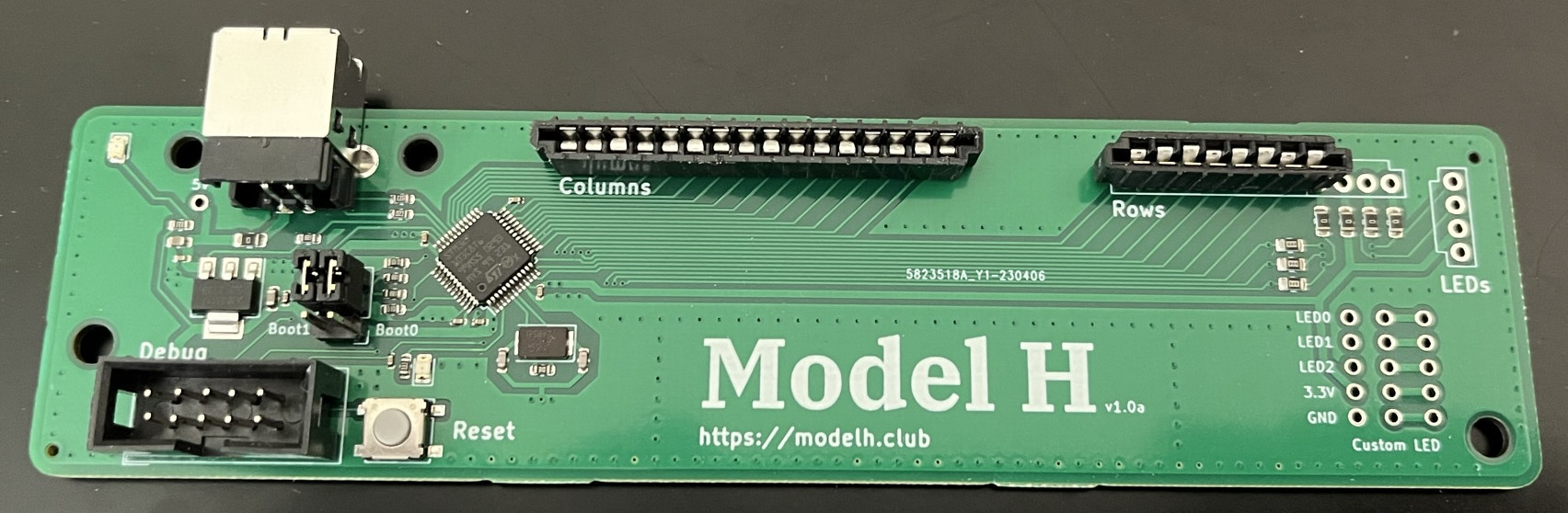
You can clearly see where to place the components on the board picture at the top of this page. Pay attention to the FFC connectors direction. Note the white lines on the board indicating the right connectors direction.
Place the two jumpers (boot0 and boot1) in 0 position (as shown on the board picture above).
Bootloader
At this point, you should have a complete controller. However, do not insert it into your keyboard just yet. You still need to program your controller and it is much easier to do it when not attached to the keyboard.
The STM32F103 micro-controller from the board does not ship with a USB bootloader. This means the USB port is not yet functional for programming. If you plug the controller to your computer, you should see the right-most LED light up, but the computer will not recognize the controller.
Initial programming requires using the debug port, as the USB port
is not yet configured. To connect it to your computer, you will need
to use a ST-Link device, such as the one shown below. Those devices
can be found on
Amazon
for ~$10.

[!TIP] If you do not want to go through the following steps for compiling your own bootloader and firmware, you can directly jump to the section below to download my pre-compiled versions.
- Install the ARM compiler
sudo apt-get install gcc-arm-none-eabi cmake build-essential - Clone the stm32f103-keyboard-bootloader locally. This repo contains the bootloader you’ll need for your keyboard.
git clone git@github.com:jberclaz/stm32f103-keyboard-bootloader.git cd stm32f103-keyboard-bootloader git checkout modelh - Build the bootloader
mkdir build && cd build
cmake ..
make -j $(nproc)
This should produce a file called
bootloader-modelh.binin thebuildfolder.
[!NOTE] If you have trouble building the booloader, it may be because your distribution is too new. I created a script that allows you to build inside a Ubuntu 20.04 Docker. To do that, just call the script
./build_inside_docker.shThis should produce the same artifact
bootloader-modelh.bin.
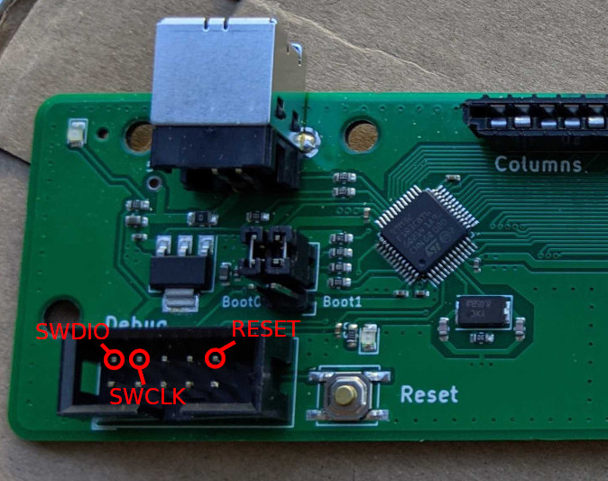
- Connect your Model H with the ST-Link device. Connect only the
SWDIO,SWCLKandRESETpins from the ST-Link to the corresponding pins on the controller’s debug port, as shown below. Do not connect the other pins.
-
Power on your controller by plugin the USB cable
- You can now flash your controller:
sudo st-flash write build/bootloader-modelh.bin 0x8000000 - After the flashing is complete, you should see a
DFUdevice when listing the USB devices withlsusb. You can now disconnect the ST-Link from your controller.
QMK Firmware
The final step in this tutorial is programming your controller with the QMK firmware. This is the firmware that will monitor the key pressed on your keyboard and communicate with the PC. Now that the bootloader is installed, flashing the firmware can be simply done through the USB port.
- Clone the QMK firmware
git clone https://github.com/qmk/qmk_firmware.git cd qmk_firmware - Install DFU-Util
sudo apt-get install dfu-util - Install the qmk binary
virtualenv -p python3 venv . venv/bin/activate pip3 install qmk - Build the firmware. This step should produce a firmware binary
ibm_model_m_modelh_default.bin.make ibm/model_m/modelh:default - Flash the firmware onto your controller. At that point, your controller should be connected via the USB cable and visible as
DFUdevice.make ibm/model_m/modelh:default:flash
Due to system configuration differences, the standard flashing method may not work. If you encounter issues, use the following alternative method, which requires root access:
sudo su
dfu-util -D ibm_model_m_modelh_default.bin
- Upon successful firmware flashing, you should see your keyboard listed among your USB devices:
$ lsusb ... Bus 001 Device 088: ID feed:b155 IBM Model M ... - To re-flash the firmware, press the onboard push button to enter
DFUmode.
Alternate firmare: QMK-Vial
QMK-Vial is an alternate firmware option. It is functionally very similar to QMK, as it was forked from this project. The main benefit of QMK-Vial is that it allows to reconfigure the key maps via a convenient web UI without having to re-flash the firmware.
To use QMK-Vial instead of QMK, follow the QMK steps above, with the following changes:
- Clone the project with
git clone https://github.com/vial-kb/vial-qmk. No need to checkout a specific branch. - Compile the firmware with
make ibm/modelh:vial - Flash the firmware with
dfu-util -D ibm_modelh_vial.bin
Pre-compiled firmware and bootloader
If you don’t want to go through all the above steps of compiling your own firmware from scratch, here are versions of QMK and QMK-Vial that I compiled myself:
Re-assembly
At this point, if everything went well, you can disconnect your Model H controller and insert it into your Model M keyboard. Make sure to handle the FFC cables very carefully when you disconnect the original controller and connect the Model H.
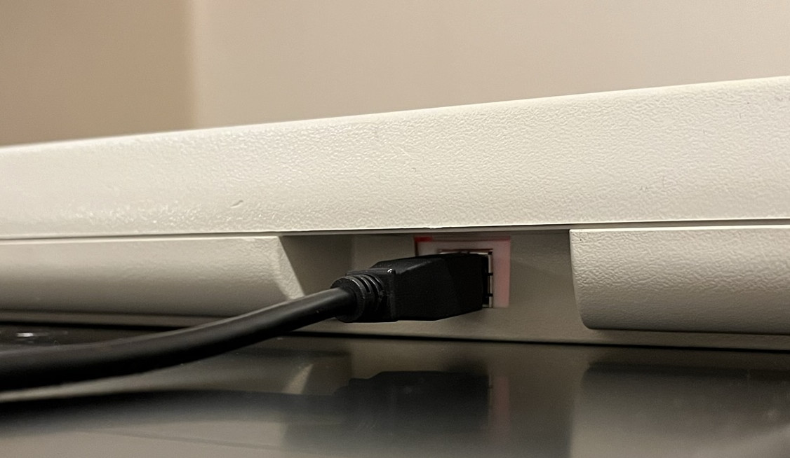
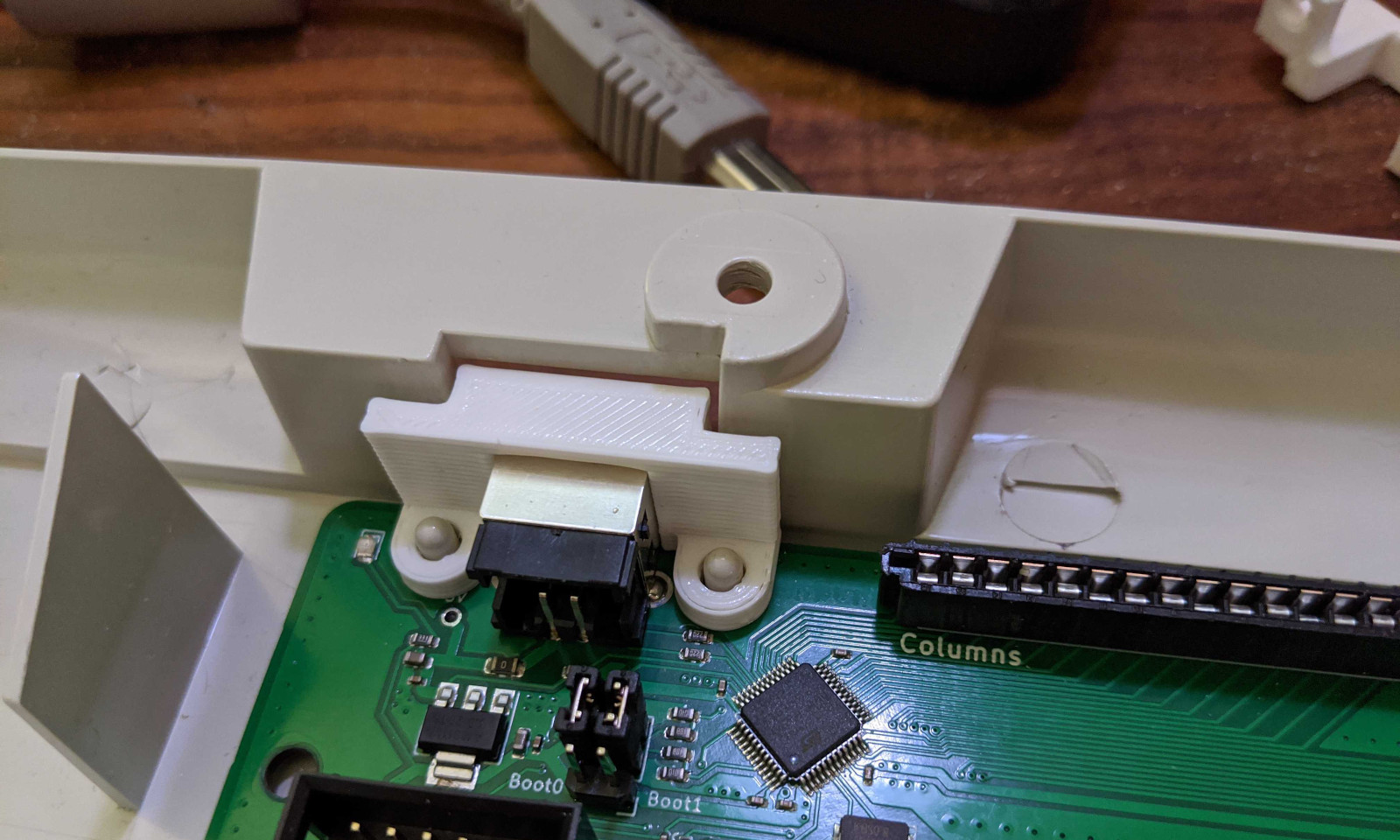
Make sure to insert the 3D printed spacer on top of the connector as shown below. This will hold the connector and the board into place.
After this, you can close the keyboard frame and replace the 4 screws. Your keyboard is now ready to be used!
Upgrading the firmware
A key advantage of the QMK firmware is that it allows you to change the keys layout. Please look at the QMK documentation to learn how to do that.
If you’ve created a new key layout and you want to flash your controller firmware once your keyboard is assembled, you don’t need to open your keyboard again. The bootloader has a nice feature that allows you to put the controller in DFU mode, without having to access the controler.
-
Disconnect your USB cable.
-
While holding down the
Esckey, plug in the USB cable again. -
Your keyboard should now appear as a
DFUdevice. It is ready to be flashed again.